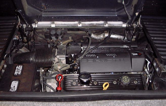
How-to install an LT1 V8 and 4T60-E into a Fiero.
Preface
There are several kits available in the aftermarket that include all of the instructions and parts needed to install a small-block Chevy V8 engine into a Fiero. However, most of these kits are made for earlier versions of the SBC, or pre-LT1 versions. Of the LT1 versions available, none to this date are configured to be 100% compatible with the 4T60-E overdrive transmission. With that being said, you can follow most of the same directions that are supplied with those kits in order to install this powertrain into a Fiero. However, there are some differences that are worth noting.

Special Considerations
The LT1 V8 (gen II SBC) is a redesigned version of the venerable gen-I SB Chevy engine that was put in production cars from 1955-1993. There are a couple of different versions of the "LT1" that you need to be on the lookout for. The 1992-1993 versions were MPI fuel injected and had a different fuel rail and intake manifold than all the other LT1's. The 1994-up LT1's were all SFI injected versions. All LT1's found in Camaros, Firebirds, and Corvettes had aluminum cylinder heads and 350 cubic inches of displacement. All LT1's found in GM B-body cars (Caprice, Impala SS, Cadillac, Buick Roadmaster, etc) had CAST IRON cylinder heads and did not make as much HP as their aluminum-headed counterparts. Furthermore, some B-body versions were not even 350 cubic inches of displacement. These look identical to the B-body LT1 but are actually L99 4.3L (265 cubic inch) V8 engines. Besides the casting numbers on the block, the easiest way to tell these apart from the 350ci LT1's are to examine the VIN number of the vehicle. The 8th VIN digit denotes engine type. All 350ci LT1's got vin designation "P" while the L99 4.3L's got vin designation "W". So be sure as to what engine you are buying before you fork over the money.
With that aside, lets get down to the nuts and bolts of the LT1. The LT1 has a unique "reverse-flow" cooling system. This means that the block and heads are cast differently to route coolant from the water pump to the cylinder heads first, then to the block, then back out to the pump. This means that a conventional SBC water pump will not work. Furthermore, the coolant does not pass to the intake manifold like earlier SBC's. The factory water pump on the LT1 is mechanically driven off the cam gear via a special splined shaft that protrudes out of the top of the timing cover. The secondary ignition distributor is located directly under the water pump which means that it has to stick further out from the block unlike earlier SBC's. This can present a serious problem when trying to use this engine in a vehicle that does not have the width to accommodate it. This was the case in the LT1/4T60-E project.
Most aftermarket kits that are available for installing an LT1 into a Fiero have you utilize the stock Fiero transmission. What most of these kits require you to do is to move the whole engine and transmission package about 2+ inches to the left of the stock location to accommodate for the extra length the water-pump adds to the engine. While this is possible when using the stock Fiero transmissions, it is not possible when using the 4T60-E. The reason why is because the 4T60-E has more bulk on the left side of the vehicle which means that you can only move it 1.75" to the left before the transmission side pan interferes with the left lower control arm. 1.75" is not enough movement to allow the use of the stock water pump and most stock crankshaft hubs. Use of these stock pieces would mean that the right side of the Fiero body chassis would have to be totally removed and there would be no room for satisfactory structural reinforcement after the engine is installed because of the proximity of right side suspension components. While it might be possible to add some material in this location, I think that enough could not be added to ensure enough strength for protection against crash dynamics and stresses that could be introduced in that area of the car. So, this means that a short crank hub for the balancer/drive pulley must be used and the factory water pump cannot be used.
The Crank Hub / Pulley
In my swap, I had a stock 1996 B-body LT1 to work with. The stock crank pulley/hub assembly was a 2-piece unit. The crank hub is shown here, unbolted from the pulley:
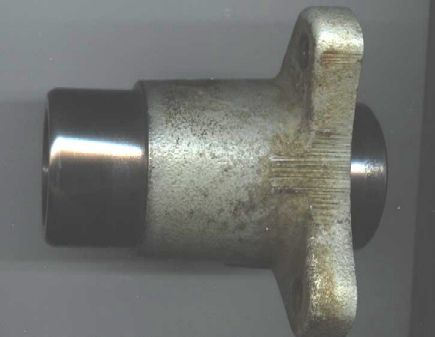
This stock hub allows the balancer pulley to sit out about 0.625" from the distributor. Since I could not afford to give up any room on this side of the engine, I had this piece machined down by 0.500". This allows the pulley to sit approx 0.125" away from the distributor. This also means that the serpentine drive system could sit that much closer to the block as well.
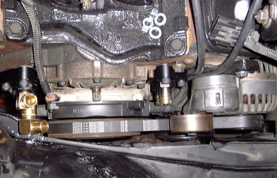
Adapter plate and automatic transmission flexplate
The LT1 or any SBC engine will not directly bolt to ANY GM transverse configuration (FWD) transmission. You will need to obtain an adapter plate, flexplate or flywheel, starter, and remote-mount oil filter system from an aftermarket supplier. These parts should come with instructions that tell you how to install them so I will not describe that process here. Furthermore, these suppliers should also sell engine mounts needed for the swap so I won't describe how to install those either. However, since most of these mounts require you to solid-mount the engine to the cradle, you must match the type of mounts for the transmission.
Transmission mounts and powertrain placement on the Fiero cradle
Since I was working with customer-supplied solid engine mounts, I needed to fabricate solid transmission mounts. I fabricated these mounts from 1/8" mild steel. The front mount was fabricated from 3 pieces which were welded together:
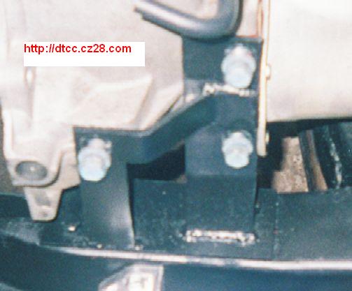
What you cannot see in this picture is that I utilized 3 of the stock Fiero cradle holes. This mount is both mounted to the transmission and to the cradle so it can be completely removed.
The rear transmission mount bolts to the transmission but is welded directly to the cradle. It is made from 2 pieces of 1/8" thick mild steel:
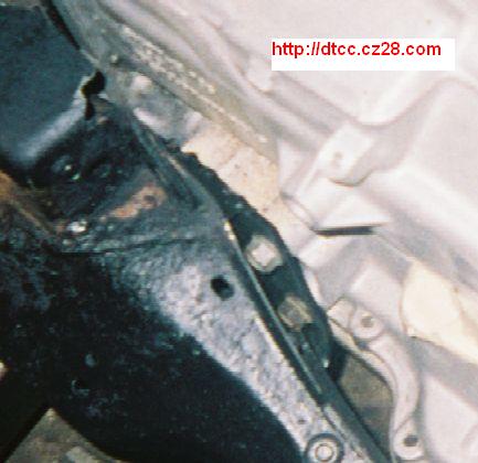
Final marking and drilling of the holes is made after final placement of the powertrain is determined. Like I said earlier, you must move the complete engine/trans assembly as far to the left as possible. This means the Fiero cradle must be notched to clear the transmission, similar to this:
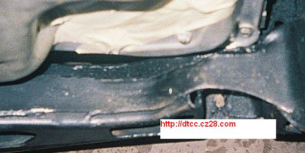
With the transmission and engine in their final resting position, the left control arm should clear the transmission side pan by about 0.125". Be sure to reinforce the areas of the cradle that you cut or notch away to clear the transmission. This can be accomplished by welding pieces of 1/8" steel onto the cradle, overlapping the areas you cut out but not interfering with the transmission. Failure to reinforce the cradle could result in poor crash or structural integrity performance that could result in bodily injury or possibly worse.
Starter and Remote Oil Filter Adapter
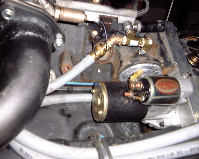
Since you can purchase these pieces from most aftermarket V8-kit suppliers, I will not discuss their installation but will show this picture of them installed:
Serpentine Accessory Belt Drive
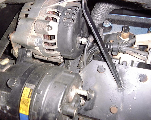
While stock Fiero components can be used, this will require you to swap out their pulleys and can be time consuming. As I had alternate parts available, I decided to use a Buick A/C compressor from an early 90's FWD car and an alternator and belt tensioner from a late 90's GM truck:
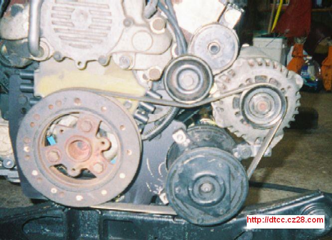
A single 6-rib, 420 inch serpentine belt drives the alternator and A/C compressor just fine. The serpentine belt tensioner is mounted to a half of a piece of 1x1 box steel tubing which in turn is mounted to the cylinder head. The alternator is mounted directly to the block and A/C compressor, and the A/C compressor is mounted directly to the aftermarket motor mount. The back of the alternator and A/C compressor are mounted to a plate which structurally ties them to the block as seen here:
Exhaust Manifolds
Because of the extra size of the 4T60-E, the standard type of manifold or header commonly used in SBC swaps in Fieros cannot be used, at least on the rear bank. Luckily, we tracked down a set of 1981 Corvette exhaust manifolds which are made form tubular steel that allowed me to modify them. The front header was basically untouched except that I cut off the stock flange and welded on a more common 3-bolt unit. The rear header did require me to weld on a tight mandrel-bend piece of 2.5" tubing in order to clear the transmission housing.
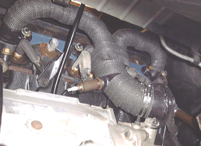
Here too I decided to make use of the 3-bolt flange. This allows the exhaust system to easily be removed for the car either for servicing or future upgrades. Notice the use of black-graphite header thermal wrap. This thermal barrier reduces under-hood temperatures up to 75% and I highly recommend its use in any engine upgrade. It also keeps more heat in the exhaust system which reduces emissions.